BGRABitmap tutorial 16
│ Deutsch (de) │ English (en) │
Home | Tutorial 1 | Tutorial 2 | Tutorial 3 | Tutorial 4 | Tutorial 5 | Tutorial 6 | Tutorial 7 | Tutorial 8 | Tutorial 9 | Tutorial 10 | Tutorial 11 | Tutorial 12 | Tutorial 13 | Tutorial 14 | Tutorial 15 | Tutorial 16 | Edit
This tutorial shows how to use textures with 3D objects.
Creating textures
To create textures, we will use the following unit. To understand how it works, you can have look at the texture tutorial. Here is the unit:
unit utexture;

{$mode objfpc}{$H+}

interface

uses
  Classes, SysUtils, BGRABitmap, BGRABitmapTypes;

function CreateGrassTexture(tx,ty: integer): TBGRABitmap;
function CreateVerticalWoodTexture(tx, ty: integer): TBGRABitmap;
function CreateWoodTexture(tx,ty: integer): TBGRABitmap;

implementation

uses BGRAGradients;

function Interp256(value1,value2,position: integer): integer; inline;
begin
     result := (value1*(256-position)+value2*position) shr 8;
end;

function Interp256(color1,color2: TBGRAPixel; position: integer): TBGRAPixel; inline;
begin
     result.red := Interp256(color1.red,color2.red,position);
     result.green := Interp256(color1.green,color2.green,position);
     result.blue := Interp256(color1.blue,color2.blue,position);
     result.alpha := Interp256(color1.alpha,color2.alpha,position);
end;

function CreateWoodTexture(tx,ty: integer): TBGRABitmap;
var
  colorOscillation, globalColorVariation: integer;
  p: PBGRAPixel;
  i: Integer;
begin
  result := CreateCyclicPerlinNoiseMap(tx,ty,1.5,1.5,1,rfBestQuality);
  p := result.Data;
  for i := 0 to result.NbPixels-1 do
  begin
    colorOscillation := round(sqrt((sin(p^.red*Pi/16)+1)/2)*256);
    globalColorVariation := p^.red;
    p^:= Interp256( Interp256(BGRA(247,188,120),BGRA(255,218,170),colorOscillation),
                    Interp256(BGRA(157,97,60),BGRA(202,145,112),colorOscillation), globalColorVariation);
    inc(p);
  end;
end;

function CreateVerticalWoodTexture(tx, ty: integer): TBGRABitmap;
var
  globalPos: single;
  colorOscillation, globalColorVariation: integer;
  p: PBGRAPixel;
  i: Integer;
  x,nbVertical: integer;
begin
  result := CreateCyclicPerlinNoiseMap(tx,ty,1,1,1,rfBestQuality);
  p := result.Data;
  x := 0;
  nbVertical := tx div 128;
  if nbVertical = 0 then nbVertical := 1;
  for i := 0 to result.NbPixels-1 do
  begin
    globalPos := p^.red*Pi/32 + nbVertical*x*2*Pi/tx*8;
    colorOscillation := round(sqrt((sin(globalPos)+1)/2)*256);
    globalColorVariation := p^.red; //round(sin(globalPos/8)*128+128);
    p^:= Interp256( Interp256(BGRA(247,188,120),BGRA(255,218,170),colorOscillation),
                    Interp256(BGRA(157,97,60),BGRA(202,145,112),colorOscillation), globalColorVariation);
    inc(p);
    inc(x);
    if x = tx then x := 0;
  end;
end;

function CreateGrassTexture(tx,ty: integer): TBGRABitmap;
var
  p: PBGRAPixel;
  i: Integer;
begin
  result := CreateCyclicPerlinNoiseMap(tx,ty,1,1,1,rfBestQuality);
  p := result.Data;
  for i := 0 to result.NbPixels-1 do
  begin
    p^ := Interp256( BGRA(0,128,0), BGRA(192,255,0), p^.red );
    inc(p);
  end;
end;

end.
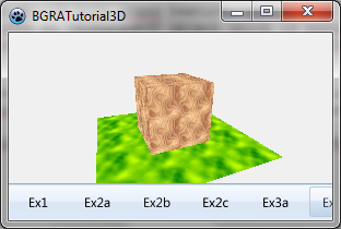
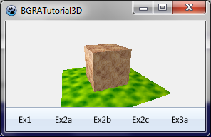
Wooden cube on the grass
Here is a unit that creates a scene with a square of grass with a wooden cube on it:
unit ex2;

{$mode objfpc}{$H+}

interface

uses
  Classes, SysUtils, BGRAScene3D, BGRABitmap, BGRABitmapTypes;

type
  { TExample2 }

  TExample2 = class(TBGRAScene3D)
    grass,wood,vWood: TBGRABitmap;

    constructor Create;
    procedure ApplyTexCoord(face: IBGRAFace3D; Times: integer = 2);
    procedure Render; override;
    destructor Destroy; override;
  end;

implementation

uses utexture;

const texSize = 128;

{ TExample2 }

constructor TExample2.Create;
var
  base,v: array of IBGRAVertex3D;
  box : IBGRAObject3D;
begin
  inherited Create;

  //create textures
  grass := CreateGrassTexture(texSize,texSize);
  vWood := CreateVerticalWoodTexture(texSize,texSize);
  wood := CreateWoodTexture(texSize,texSize);

  //create ground
  with CreateObject(grass) do
  begin
    base := MainPart.Add([-50,20,-50, -50,20,50, 50,20,50, 50,20,-50]);
    ApplyTexCoord(AddFace(base),4);
  end;

  //create wooden box
  box := CreateObject(vWood);
  with box do
  begin
    v := MainPart.Add([-1,-1,-1, 1,-1,-1, 1,1,-1, -1,1,-1,
                       -1,-1,+1, 1,-1,+1, 1,1,+1, -1,1,+1]);

    ApplyTexCoord(AddFace([v[0],v[1],v[2],v[3]]));
    ApplyTexCoord(AddFace([v[4],v[5],v[1],v[0]],wood));
    ApplyTexCoord(AddFace([v[7],v[6],v[5],v[4]]));
    ApplyTexCoord(AddFace([v[3],v[2],v[6],v[7]],wood));
    ApplyTexCoord(AddFace([v[1],v[5],v[6],v[2]]));
    ApplyTexCoord(AddFace([v[4],v[0],v[3],v[7]]));

    MainPart.Scale(20);
  end;
  //RemoveObject(box);

  ViewPoint := Point3D(-40,-40,-100);
end;

procedure TExample2.ApplyTexCoord(face: IBGRAFace3D; Times: integer);
begin
  with face do
  begin
    TexCoord[0] := PointF(0,0);
    TexCoord[1] := PointF(texSize*Times-1,0);
    TexCoord[2] := PointF(texSize*Times-1,texSize*Times-1);
    TexCoord[3] := PointF(0,texSize*Times-1);
  end;
end;

procedure TExample2.Render;
begin
  inherited Render;
end;

destructor TExample2.Destroy;
begin
  grass.free;
  wood.free;
  vWood.free;
  inherited Destroy;
end;

end.
First the needed textures are created. The grass is created as an object with grass texture, defined by 4 vertices. The texture is defined as a parameter to the CreateObject function. The AddFace returns an IBGRAFace3D object which is passed to the custom procedure ApplyTexCoord. This procedure sets the TexCoord property for each vertex of the face. These coordinates are floating point pixel-centered coordinates.
The wooden box is created as an object with vertical wood texture. The vertices define a cube with unit coordinates. It is scaled later on. When creating top and bottom faces, another texture is applied which is a perpendicular wood texture.
Finally the view point is set. To be a little bit from the side. The default value is (0,0,-100). This way the scene has some perspective.
Lighting and normals
It is possible to add some lighting:
    LightingNormal:= lnFace;

    AmbiantLightness := 0.25;
    with CreateObject do
    begin
      AddPointLight(MainPart.Add(-100,-80,0),140,0.5);
    end;
Here lightness is used like in the previous tutorial. But the light is a point. To define a vertex, it is necessary to create an object to contain it. It is possible later to move the light. The further an object is from the light, the darker it is. The optimal distance parameter specifies the distance for which the light intensity is defined by the next parameter. It means that if the object is at a distance of 140, the lightness added will be 0.5.
Notice that we defined LightingNormal to lnFace. This means that the light is computed considering the faces are flat. There is no roundiness added to the lighting. This will be useful in other cases but not here.

