fpvectorial
Introduction
FPVectorial offers support to read, modify and write vectorial images.
Its counterpart library is fcl-image, which works with raster images. FPVectorial comes with a unit which allows to draw a vectorial image to a TFPCustomCanvas, but no routines are provided to convert raster images to vectorial images.
Download
fpvectorial is distributed along with Lazarus. You can find it in folder components/fpvectorial of your Lazarus installation.
If you have a release version of Lazarus and want the latest version of fpvectorial you can download it by svn from
svn co http://svn.freepascal.org/svn/lazarus/trunk/components/fpvectorial fpvectorial
Downloading the fpvviewer project:
svn co https://lazarus-ccr.svn.sourceforge.net/svnroot/lazarus-ccr/applications/fpvviewer fpvviewer
Current file list
FPVectorial is located in the Lazarus directory components/fpvectorial.
The central unit is fpvectorial.
Readers for various image formats
- pdfvectorialreader - Read support for PDF files, supports compression, only reads the first page
- avisocncgcodereader - Read support for the G-Code from the Aviso CNC machine
- cdrvectorialreader - Initial work of a reader support for Corel Draw CDR files
- dxfvectorialreader - Read support for DXF, the Drawing eXchange Format utilized by the AutoCAD
- svgvectorialreader - Read support for SVG
- epsvectorialreader - Read support for Encapsulated PostScript
- wmfvectorialreader - Read support for WMF (Windows metafile, cross-platform!)
Writers for various image formats
- avisocncgcodewriter - Write support for the G-Code from the Aviso CNC machine
- svgvectorialwriter - Write support for SVG. The most advanced writer at the moment. Supports lines, curves and text. Supports pen color and width.
Other units
- fpvtocanvas - Converts a vectorial document to a TFPCustomCanvas descendent (like TCanvas). Essentially converts the vectorial image to a raster image
- fpvutils - Utility functions which don't belong to fpvectorial.pas or that would bring unwanted dependencies to it. Color conversion functions.
- pdfvrlexico, pdfvrsemantico, pdfvrsintatico, avisozlib - Other units from the PDF reader, don't use directly
Formats
The PDF format is developed by Adobe (tm) and it is fully documented. Inside, PDF is simply text, so it is rather easy to parse, but parts of this text are usually can be compressed.
Link to the PDF Reference: http://www.adobe.com/devnet/pdf/pdf_reference.html
CorelDraw
Corel does not release public documentation for its CorelDraw file format. Any information about this format depends on reverse engineering and guessing. The format is binary and consists of a tree of chunks.
See also fpvectorial#fpcorelexplorer
SVG
Scalable Vectorial Graphics (SVG) is a standard from W3C for vectorial graphics. It is the native format of Inkscape and stores its data as a single, uncompressed XML file with the extension ".svg".
Link to the specification: http://www.w3.org/TR/SVG/
A very serious shortcoming in SVG is that it does not allow real world units to be specified in the drawing routines, only pixel values accepted, which makes it impossible to have a document with real world units. This can be worked around by simply hardcoding to a fixed DPI resolution, which is 90 DPI for Inkscape. Read more here:
- http://stackoverflow.com/questions/1346922/svg-and-dpi-absolute-units-and-user-units-inkscape-vs-firefox-vs-imagemagick
- http://www.inkscapeforum.com/viewtopic.php?f=16&t=5904
- http://www.inkscapeforum.com/viewtopic.php?f=16&t=3700&p=17179&hilit=units+path#p17179
Following Inkscape and the Opera Browser, FPVectorial also hardcodes to 90 DPI.
As of February 2014 support for SVG is partial.
DXF
The Drawing eXchange Format from Autodesk AutoCAD. This format is documented, but the quality of the documentation is rather low, lacking adequate explanations.
The format itself is rather simple, composed by text. Each unit is composed of two lines, the first one being a number describing the type of data and then another line with the value itself, which might be text or a number.
The most common problem in other DXF reading libraries is that they don't support the actual DXF writen by newer versions of AutoCAD. This is not the case with fpvectorial, which was tested with AutoCAD 2000 and also the previous simpler formats.
Link to the documentation:
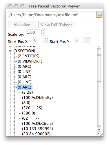
The software fpvviewer can be utilized to show the internal structure of a DXF file. This software can be found in the lazarus-ccr svn in applications/fpvviewer. More info here: fpvectorial#fpvviewer
WMF
The Windows Metafile (WMF) format was originally designed for Microsoft Windows in the 1990s. The files can contain both vector graphics and bitmap components and consist of a list of drawing commands with parameters which are originally passed directly to the Windows Graphics Device Interface (GDI); in fpvectorial, however, they are converted to graphics objects which makes the format platform-independent.
The file structure is documented at http://msdn.microsoft.com/en-us/library/cc250370.aspx
PostScript
PostScript is a graphics drawing programming language and fpvectorial has an interpreter which can execute PostScript and convert its commands into its internal format. This is done by reader modules, for example epsvectorialreader. The interpreter is separated into a Tokenizer and an Executer. The tokens are classified into 3 types: Procedures, ExpressionTokens and Comments. Procedures are inside a {..} block in PostScript and in FPVectorial they are not tokenezed in the first pass, but instead on the first usage. The entire document is tokenized in one run, before executing the tokens, except for the procedures. The PostScript interpreter contains a Stack and a lookup Dictionary, as specified in PostScript.
PostScript can be embedded into various formats, and the interpreter currently supports the EPS format.
References:
- http://en.wikipedia.org/wiki/Encapsulated_PostScript
- http://partners.adobe.com/public/developer/en/ps/PLRM.pdf
LAS
LAS is geospatial data encoded in the ASPRS LASer (LAS) file format, which exists in versions 1.0, 1.1, 1.2, 1.3 and 1.4. Version 2.0 does not yet exist as of December 2011.
References:
- http://en.wikipedia.org/wiki/LibLAS
- http://www.asprs.org/a/society/committees/lidar/lidar_format.html
- http://trac.liblas.org/wiki/Software
- http://www.cs.unc.edu/~isenburg/lastools/
- http://www.fugroviewer.com/
- Example las file: www.appliedimagery.com/downloads/sampledata/Serpent%20Mound%20Model%20LAS%20Data.las
- Specification docs up to 1.3: http://www.asprs.org/a/society/committees/standards/lidar_exchange_format.html
- Specification for 1.4: http://www.asprs.org/Press-Releases/LAS-1-4-Draft-Specification-Released-by-ASPRS.html
Types of data in FPVectorial
FPVectorial holds lists of three types of objects: paths, text and entities.
Essentially paths are sequences of points, through which run lines and bezier curves. A path can be a line, a bezier, a polyline, a polybezier or any combination of these elements. The main characteristic of paths is that they can be utilized to guide a milling machine, also known as CNC machine, into physically executing the drawing. Before being able to execute a drawing which contains either text or entities in a CNC machine, these items need to be converted to paths.
Text, just like the name says are strings drawn with fonts.
Entities are things like circles, arcs, ellipses, rotated ellipses, etc.
Usage examples
Format conversion
This example loads a PDF, converts it to G-Code and writes the G-Code to a TStrings descendent
uses
  fpvectorial, pdfvectorialreader, avisocncgcodewriter;

var
  Vec: TvVectorialDocument;
begin
  if dialogoAbrir.Execute() then
  begin
    Vec := TvVectorialDocument.Create;
    try
      Vec.ReadFromFile(dialogoAbrir.FileName, vfPDF);
      Vec.WriteToStrings(synCodigo.Lines, vfGCodeAvisoCNCPrototipoV5);
    finally
      Vec.Free;
    end;
  end;
end;
Adding paths, bezier lines and text
This example shows how to add various elements.
{
Author: Felipe Monteiro de Carvalho

License: Public Domain
}
program fpvwritetest;

{$mode objfpc}{$H+}

uses
  fpvectorial, svgvectorialwriter;

const
  cFormat = vfSVG;
  cExtension = '.svg';
var
  VecDoc: TvVectorialDocument;
  Vec: TvVectorialPage;
  s : String;
begin
  VecDoc := TvVectorialDocument.Create;
  try
    // All documents are 10cm x 10cm
    VecDoc.Width := 100;
    VecDoc.Height := 100;

    Vec := VecDoc.AddPage();
    Vec.Width := VecDoc.Width;
    Vec.Height := VecDoc.Height;

    // ...

    // multi_test_1     Combines various elements
    Vec.Clear;
    Vec.StartPath(0, 20);
    Vec.AddLineToPath(30, 30);
    Vec.EndPath();
    Vec.StartPath(0, 0);
    Vec.AddLineToPath(100, 0);
    Vec.AddLineToPath(100, 100);
    Vec.AddLineToPath(0, 100);
    Vec.AddLineToPath(0, 0);
    Vec.EndPath();
    Vec.StartPath(0, 0);
    Vec.AddLineToPath(10, 10);
    Vec.AddBezierToPath(10, 20, 20, 20, 20, 10);
    Vec.AddLineToPath(30, 0);
    Vec.EndPath();
    Vec.AddText(10, 10, 0, '10,10 Some text in english.');
    s := '20, 20 Mówić, cześć, Włosku, Parabéns.';
    Vec.AddText(20, 20, 0, s);
    s := '30, 30 森林,是一个高密';
    Vec.AddText(30, 30, 0, s);
    VecDoc.WriteToFile('multi_test_1' + cExtension, cFormat);
  finally
    VecDoc.Free;
  end;
end.
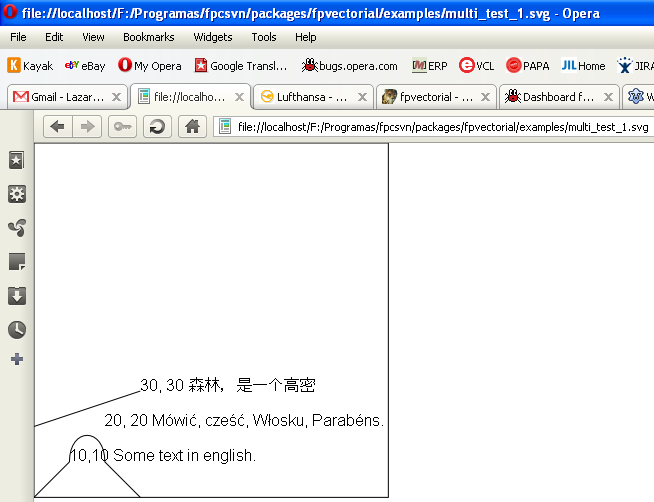
And here is the output of this example when rendered by the Opera Browser:
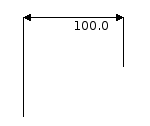
Adding Aligned Coordinates
One can either add horizontal coordinates:
Vec.AddAlignedDimension(Make2DPoint(100, 50), Make2DPoint(200, 100), Make2DPoint(100, 150), Make2DPoint(200, 150));
Or add vertical coordinates:
Vec.AddAlignedDimension(Make2DPoint(50, 250), Make2DPoint(100, 200), Make2DPoint(150, 250), Make2DPoint(150, 200));
Rendering the image into a TCanvas
To render a vectorial image into a TCanvas or TFPCustomCanvas use the unit fpvtocanvas and its routines:
unit fpvtocanvas;
//..
{@@
  This function draws a FPVectorial vectorial image to a TFPCustomCanvas
  descendent, such as TCanvas from the LCL.

  Be careful that by default this routine does not execute coordinate transformations,
  and that FPVectorial works with a start point in the bottom-left corner, with
  the X growing to the right and the Y growing to the top. This will result in
  an image in TFPCustomCanvas mirrored in the Y axis in relation with the document
  as seen in a PDF viewer, for example. This can be easily changed with the
  provided parameters. To have the standard view of an image viewer one could
  use this function like this:

  DrawFPVectorialToCanvas(ASource, ADest, 0, ASource.Height, 1.0, -1.0);
}
procedure DrawFPVectorialToCanvas(ASource: TvVectorialPage;
  ADest: TFPCustomCanvas;
  ADestX: Integer = 0; ADestY: Integer = 0; AMulX: Double = 1.0; AMulY: Double = 1.0);
And below an example taken from lazarus-ccr/application/fpvviewer
uses fpvtocanvas;

procedure TfrmFPVViewer.btnVisualizeClick(Sender: TObject);
const
  FPVVIEWER_MAX_IMAGE_SIZE = 1000;
  FPVVIEWER_MIN_IMAGE_SIZE = 100;
  FPVVIEWER_SPACE_FOR_NEGATIVE_COORDS = 100;
var
  Vec: TvVectorialDocument;
  CanvasSize: TPoint;
begin
  // First check the in input
  //if not CheckInput() then Exit;

  notebook.PageIndex := 0;

  Drawer.Clear;

  Vec := TvVectorialDocument.Create;
  try
    Vec.ReadFromFile(editFileName.FileName);

    // We need to be robust, because sometimes the document size won't be given
    // also give up drawing everything if we need more then 4MB of RAM for the image
    // and also give some space in the image to allow for negative coordinates
    if Vec.Width * spinScale.Value > FPVVIEWER_MAX_IMAGE_SIZE then CanvasSize.X := FPVVIEWER_MAX_IMAGE_SIZE
    else if Vec.Width < FPVVIEWER_MIN_IMAGE_SIZE then CanvasSize.X := Drawer.Width
    else CanvasSize.X := Round(Vec.Width * spinScale.Value);
    if CanvasSize.X < Drawer.Width then CanvasSize.X := Drawer.Width;

    if Vec.Height * spinScale.Value > FPVVIEWER_MAX_IMAGE_SIZE then CanvasSize.Y := FPVVIEWER_MAX_IMAGE_SIZE
    else  if Vec.Height < FPVVIEWER_MIN_IMAGE_SIZE then CanvasSize.Y := Drawer.Height
    else CanvasSize.Y := Round(Vec.Height * spinScale.Value);
    if CanvasSize.Y < Drawer.Height then CanvasSize.Y := Drawer.Height;

    Drawer.Drawing.Width := CanvasSize.X;
    Drawer.Drawing.Height := CanvasSize.Y;
    Drawer.Drawing.Canvas.Brush.Color := clWhite;
    Drawer.Drawing.Canvas.Brush.Style := bsSolid;
    Drawer.Drawing.Canvas.FillRect(0, 0, Drawer.Drawing.Width, Drawer.Drawing.Height);
    DrawFPVectorialToCanvas(
      Vec.GetPage(0),
      Drawer.Drawing.Canvas,
      FPVVIEWER_SPACE_FOR_NEGATIVE_COORDS,
      Drawer.Drawing.Height - FPVVIEWER_SPACE_FOR_NEGATIVE_COORDS,
      spinScale.Value,
      -1 * spinScale.Value);
    Drawer.Invalidate;
  finally
    Vec.Free;
  end;
end;
Coordinates in FPVectorial
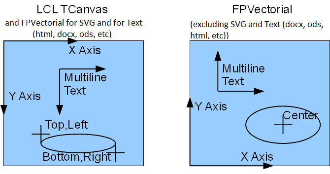
It is important to note that FPVectorial works with two different systems of coordinates: Top-Left Coordinates and Bottom-Left Coordinates. TCanvas uses the coordinates from the Windows API, with the origin in the top-left corner and with the X axis growing to the right and the Y axis growing to the bottom. FPVectorial, besides supporting this system, also supports another one for drawing formats where this system is native such as CAD software, Inkscape, the Mac OS X APIs (Carbon and Cocoa), etc. In FPVectorial the origin is in bottom-left for all vectorial graphics formats except SVG. The X axis grows to the right and the Y axis to the top. The origin is in the top-left for SVG and all text document formats such as DOCX.
When the coordinates do not match TCanvas, one should be careful when converting coordinates between TCanvas and FPVectorial. To convert coordinates between TCanvas and FPVectorial, one needs the height of the Canvas. The following routine from the unit fpvutils can be used to execute this conversion:
{@@ Converts the coordinate system from a TCanvas to FPVectorial
   The basic difference is that the Y axis is positioned differently and
   points upwards in FPVectorial and downwards in TCanvas.
   The X axis doesn't change. The fix is trivial and requires only the Height of
   the Canvas as extra info.
}
function CanvasCoordsToFPVectorial(AY: Integer; AHeight: Integer):
Integer; inline;
begin
 Result := AHeight - AY;
end;
And there is also a difference regarding the text positioning. In TCanvas.TextOut the text is positioned based on the top-left coordinates of the text area. In fpvectorial it is based on the bottom-left. Again, there is a convenient routine in the unit fpvutils to convert between the coordinate systems:
{@@
  LCL Text is positioned based on the top-left corner of the text.
  Besides that, one also needs to take the general coordinate change into account too.

  @param ACanvasHeight Should receive TCanvas.Height
  @param ATextHeight   Should receive TFont.Size
}
function CanvasTextPosToFPVectorial(AY: Integer; ACanvasHeight, ATextHeight: Integer): Integer;
begin
  Result := CanvasCoordsToFPVectorial(AY, ACanvasHeight) - ATextHeight;
end;
More examples
Since fpvectorial is part of the Lazarus distribution, you can find the examples in the folder components/fpvectorial/examples of your Lazarus directory.
fpvviewer
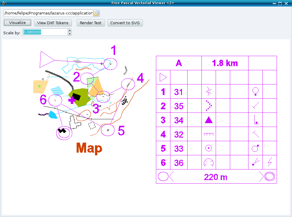
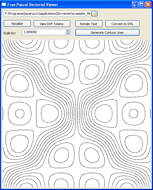
The Free Pascal Vectorial Viewer is a sample application which implements a simple CAD viewer using fpvectorial.
Besides being able to visualize vectorial drawings, this software can also help in exploring the internal structure of DXF file:
Its source code can be found in the Lazarus-CCR in the directory application/fpvviewer
Link to download the zipped source snapshot of this application: https://sourceforge.net/p/lazarus-ccr/svn/HEAD/tree/applications/fpvviewer/
Link to download the entire Lazarus-CCR repository from subversion:
svn co https://lazarus-ccr.svn.sourceforge.net/svnroot/lazarus-ccr lazarus-ccr
Contour line generation
fpvviewer can generate contour lines from .raw files. These files can be generated with fpv3dviewer
FPVectorial Debug Tokens
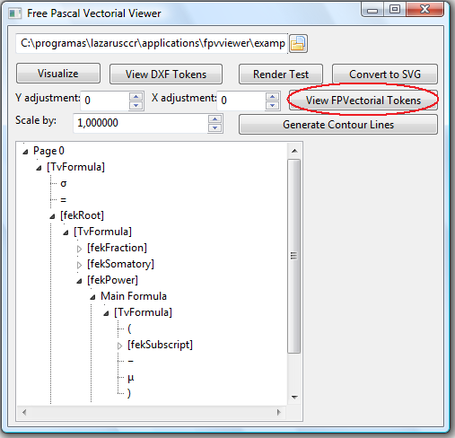
FPVViewer can be utilized to see the internal debug tokens from fpvectorial, see:
fpcorelexplorer
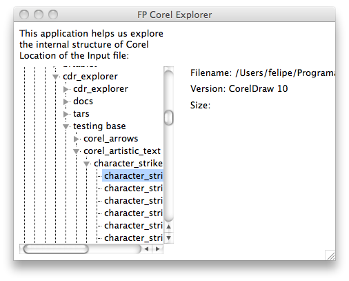
An application was developed for helping studying the CDR file format. At the moment this application can identify the version of CorelDraw files. It is located in fpctrunk/packages/fpvectorial/examples/fpcorelexplorer.lpi
fpv3dviewer
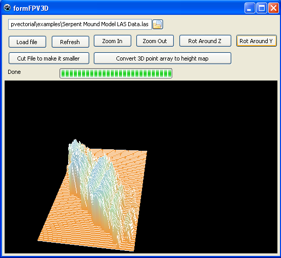
One of the examples of fpvectorial located in lazarus/components/fpvectorial/examples/fpv3dviewer.lpi is a 3D viewer.
Articles about fpvectorial
- Revista Clube Delphi Edition #131: http://www.devmedia.com.br/assgold/listmag.asp?site=3
Go to back Packages List
